Displacement 置换
Introduction
引言
Displacement mapping is a texture-based technique used to physically displace tessellated geometry. It can be controlled by either a vector texture or height map texture, which is used to perturb the surface geometry. Unlike its cheaper 'sister' shader (Bump Map), displacement mapping affects shadows, since the geometry is actually perturbed.
位移贴图是一种基于纹理的技术,用于物理替换镶嵌的几何图形。它可以通过矢量纹理或高度贴图纹理控制,用于扰乱表面几何形状。不像它的姐妹着色器(凹凸贴图) ,位移贴图影响阴影,因为几何实际上是扰乱的。
To chain displacement-maps together we supply a Displacement Blender shader node which has been optimized to efficiently blend resultant displacement vectors together.
为链位移-地图一起,我们提供了一个位移混合器着色节点,已经优化,有效地混合生成的位移矢量在一起。
The output of this shader is a displacement vector, which when attached to the material displacement input will result in a perturbed surface position and normal.
这个着色器的输出是一个位移,当连接到材质位移输入时,会导致表面位置和法线受到干扰。
Prerequisites
先决条件
To make displacement mapping work, you'll need to enable tessellation and displacement on your object.
为了使位移贴图工作,你需要启用镶嵌和位移对你的对象。
Please see the Tessellation and Displacement page for instructions and information on how to do that.
请看镶嵌和位移页面的指示和信息,如何做到这一点。
Displacement Parameters
排水量参数
TexMap
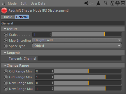
Connect a texture sampling shader node here to set the displacement map input.
在这里连接一个纹理取样着色器节点来设置置换贴图输入。
Scale
比例
This scales the displacement value that is read from the texture. A value of 0.0 effectively disables the technique, yielding the original surface. Greater values increase the displacement effect. Negative values invert the direction of the displacement. The default is 1.0.
这可以缩放从纹理读取的位移值。0.0有效地禁用该技术,产生原始表面。更大的值增加了置换效应。负值与位移的方向相反。默认值是1.0。
Map Encoding
地图编码
This determines the type of displacement to do, given the texture input type:
这决定了要做的置换类型,给定纹理输入类型:
- Vector – a floating point displacement vector 矢量-一个浮点位移
- Height Field – a height-field/bump-map scale along the surface normal 沿着表面法线的高度场/凹凸贴图比例尺
Space Type
空间类型
When computing vector displacement, it can be done in the following geometry space:
当计算矢量位移时,可以在以下几何空间中完成:
- Object – the displacement map is expected to fit onto the object geometry 对象-位移映射预计适合对象的几何形状
- Tangent – the displacement map can be applied to any geometry, providing it has a known uv tangent space 切线-位移映射可以适用于任何几何形状,提供它有一个已知的紫外线切线空间
Only applicable to Vector type Map Encoding.
只适用于矢量类型映射编码。
UV Set
紫外线
Specify a UV Set other than the default here.
在这里指定一个除了默认值以外的 UV 设置。
Change Range
改变范围
Old Range Min / Max
旧靶场最小/最大靶场
The range of values that are read from the displacement/bump texture.
从位移/凹凸纹理读取的值范围。
New Range Min / Max
新航程最小/最大
The new range the values will be mapped to.
值映射到的新范围。
Displacement Example 置换例子
Here is an example of how displacement mapping can enhance the detail of simple geometry.
这里有一个例子来说明位移贴图如何增强简单几何的细节。
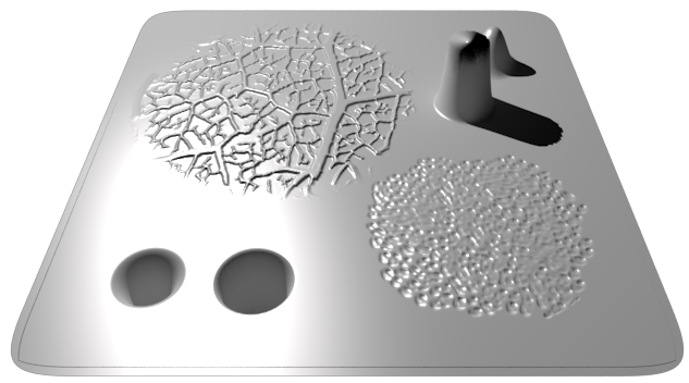
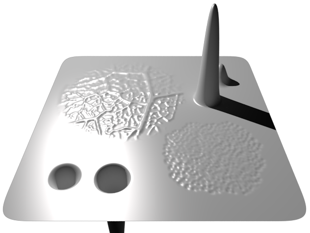
The scene shows a plane that has been tessellated with the default mesh tessellation/displacement parameters. A displacement shader has been connected to the material displacement input and the displacement image is a vector map.
场景显示了一个镶嵌了缺省网格镶嵌/位移参数的平面。位移着色器连接到材料位移输入端,位移图像为矢量图。
Notice how the 'Scale' parameter of the displacement shader is very small - this is because displacement is applied in world units and in this particular example, the mesh is very small, so we only need a small amount of displacement to yield a dramatic change in the geometry shape.
注意位移着色器的“缩放”参数是非常小的——这是因为位移适用于世界单位,在这个特殊的例子中,网格是非常小的,所以我们只需要一个小的位移量就可以在几何形状上产生巨大的变化。
Here is the resultant render. See how the otherwise flat surface has geometric detail? The displacement vector map contains a different test in each quadrant. Top-left demonstrates fine perturbation high frequency detail coming out of the plane. Top-right demonstrates large perturbation low frequency detail coming out of the plane. Bottom-left demonstrates large detail, but as an indentation, going into the plane and bottom-right demonstrates fine detail going into the plane. More importantly, note how the top-right tower appears distorted and the lighting looks wrong - this is because the 'Max Displacement' of the mesh is default to 1.0 and so the displacement is being capped to that.
这是渲染的结果。看看原本平坦的表面如何具有几何细节?位移地图在每个象限包含一个不同的测试。左上角显示出来自飞机的精细微扰高频细节。右上角显示了从飞机出来的大扰动低频细节。左下角显示了大量的细节,但是作为一个缩进,进入平面和右下角显示了进入平面的细节。更重要的是,注意如何顶部右塔看起来扭曲和照明看起来错误-这是因为’最大位移’的网格是默认为1.0,所以位移被限制到那。
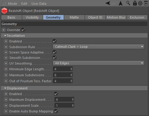
You can see here that to compensate for the stumpy tower, we increase the 'Max Displacement' setting in the mesh properties to 4.
你可以在这里看到,为了补偿树桩塔,我们增加了’最大位移’的网格属性设置为4。
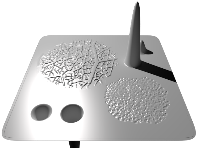
Here is the resultant render. See how the tower now stands in all its glory. At the bottom of the render you can also now see the indented tower.
这是渲染的结果。看看这座塔现在是多么的雄伟壮丽。在渲染底部,你现在也可以看到缩进的塔。
This last image shows what the render would look like without 'Bump Mapping' enabled.
最后一张图片显示了没有激活凹凸贴图的渲染效果。
The low frequency detail towers don't look any different, but the finer, high frequency detail parts now look blurry. Without 'Bump Mapping', you would have to tessellate the mesh to a ridiculous level to get the same quality of detail, which of course, is not recommended.
低频细节塔看起来没有任何不同,但更细致,高频细节部分现在看起来模糊。如果没有“凹凸贴图”,你将不得不把网格分为一个荒谬的级别,以获得相同的细节质量,当然,这是不推荐的。


赶快留个言打破零评论!~